USS Holland Switchboard
Computer Model of Switchboard
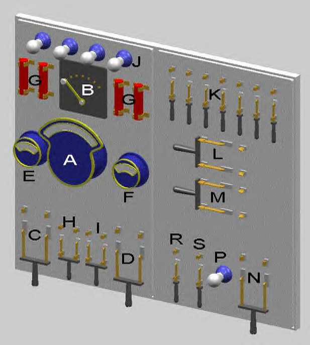
The computer model of the USS Holland switchboard is based on a description of the switchboard in the Type 7 operating manual:
A – Voltmeter
B – 7 Point Voltmeter Switch used to connect the voltmeter to any one of seven circuits.
C – Large Double Pole Single Throw switch for the forward battery
D – Large Double Pole Single Throw switch for the after battery
E – Forward battery ammeter
F – After battery ammeter
G – Fuses
H – D.P.S.T. switch for lighting circuit
I – D.P.S.T. switch for engine room ventilating fan
J – Four lamps serve as ground detection devices
K - Seven S.P.S.T. motor starting switches
L - D.P.D.T. for reversing the armature circuit
M - forward connects the forward and after battery in parallel,
aft connects the forward and after battery in series
N - D.P.D.B.S.T. switch for dynamo field circuit
P - lamp used to break the electric arc that follows opening of the switch
R - S.P.S.T. switch for the forward engine ignitor plug
S - S.P.S.T. switch for the after engine ignitor plug
ÓCopyright 1999,2000,2001,2002 Gary McCue