USS Holland Seawater Systems
Computer Model of Seawater System
The seawater systems consist of the following equipment:
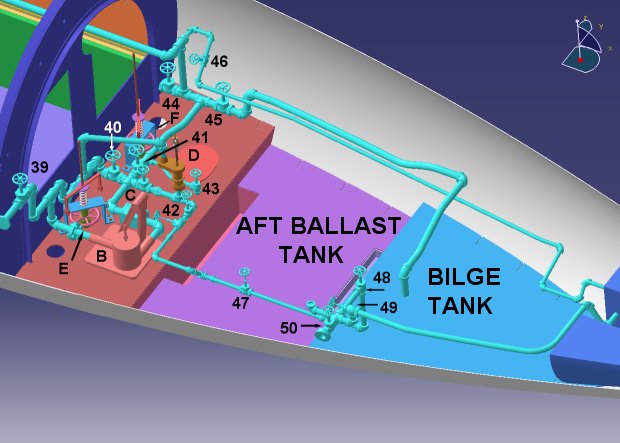
A – Kingston valve used to flood the forward trim tank
B – Belt driven bilge pump
C – Strainer
D – handpump
E – Kingston valve for flooding the main ballast tank
F – Kingston valve for flooding the main ballast tank
Valves:
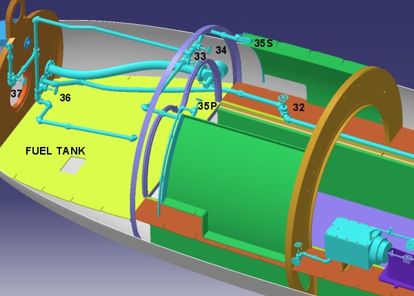
32 - connects the fore and aft trim tanks
33 - drains the torpedo tube into the port compensating tank
34 - drains the torpedo tube into the starboard compensating tank
35P - vents the port compensating tank
35S - vents the starboard compensating tank
36 - drains the torpedo tube into the forward trim tank
37 - drains the forward trim tank overboard
38 - air compressor cooling water inlet
38' - air compressor cooling water outlet
39 - outboard connection for bilge pumps
40 - outboard connection for handpump
41 - connects ballast tanks and bilge tanks to pump
42 - connects ballast tanks and bilge tanks to handpump
43 - connects aft ballast tank to bulge pump
44 - connects the main ballast tank to the bilge pump
45 - connects the bilge tanks to the bilge pump
46 - connects the aft trim tanks to the bilge pump
47 - connects the bilge tanks to the handpump
48 - connects the gas engine circulating pump to the sea
49 - to aft trim tanks
50 - overboard connection
Diagram developed from Piping Plan, National Archives
The USS Holland used seawater to cool the gasoline engine and air compressor. Water was admitted to the main and aft ballast tank via Kingston valves. Water could also be admitted to the forward and aft trim tanks via hull valves. A belt driven bilge pump was piped such that it could move water from any one tank to another, or pump the water overboard. A hand-operated pump was provided for backup. Upon surfacing, the ballast tanks and trim tanks were emptied by opening the hull valves and forcing the water out with compressed air.
ÓCopyright 1999,2000,2001,2002 Gary McCue