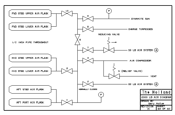

The 2000 psi subsystem included the following equipment:
Air Compressor
The air compressor was a slow speed reciprocating device driven by the 10 h.p. electric motor through a series of gears. This compressor was theoretically capable of compressing air to 2000 psi, however there are several reports of leaking seals and other problems that frequently prevented the compressor from achieving 2000 psi.
Two 2000 psi air flasks were located forward between frame 24 and 29 on the starboard side. Two more flasks were located in the midbody across from the air compressor (between frames 14 and 19 on the starboard side). Two additional flasks were located aft, outboard of the electric motor and gas engine - one on the port side and one on the starboard side between frames 7 and 12. These flasks were constructed of 13/16 inch thick steel and contained 22 cubic feet of compressed air.
| Valve 1 | served to isolate the aft flasks. |
| Valve 2 | provided a means of bypassing the reducing and supplying 2000 psi air to the 50 psi system.valve |
| Valve 3 | served to isolate the midbody tanks. |
| Valve 4 | isolated the air compressor. |
| Valve 5 | was the relief valve at the air compressor. |
| Valve 6 | isolated the forward systems (valve 8, 9 and 10). |
| Valve 7 | controlled the supply of air to the reducing valve supplying the 50 psi compressed air subsystem. |
| Valve 8 | supplied 2000 psi air for charging torpedoes. |
| Valve 9 | supplied 2000 psi air to the dynamite gun. |
| Valve 10 | isolated the forward tanks. |
All piping in the 2000 psi system was 1/2 inch nominal diameter.
ÓCopyright 1999,2000,2001,2002 Gary McCue