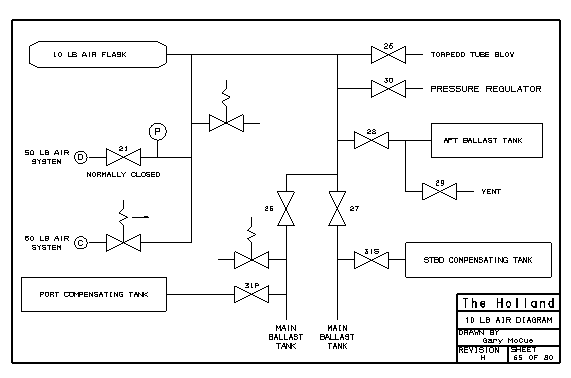

The 10 psi subsystem included the following equipment:
One 10 psi air flask
The 10 psi flask was located forward on the port side between the 50 psi flasks.
This valve is labelled on the piping arrangment drawing, but is mentioned in the ship specification.
| Valve 25 | used to blow out the torpedo tube. | |
| Valve 26 | used to blow out or vent the main ballast tank (port side). | |
| Valve 27 | used to blow out or vent the main ballast tank (starboard side). | |
| Valve 28 | used to blow out the aft ballast tank. | |
| Valve 29 | used to vent the aft ballast tank into the submarine. | |
| Valve 30 | the controlling valve for a pressure regulator. | |
| Valve 31' | for draining the starboard compensating tank into the main ballast tank. |
The 10 psi system was 1 inch nominal diameter throughout.
ÓCopyright 1999,2000,2001,2002 Gary McCue